Part 7/8
Last time we talked about how a network packet transverses a VPN tunnel, today we will discuss how a NAT device works. Here is where we left off last time with our network packet:
L2-[Source MAC: 04-04-04-04-04-04 | Destination MAC: 05-05-05-05-05-05]
L3-[Source IP: 10.1.1.100 | Destination IP: 11.1.1.100]
L4-[Source Port: TCP 1025 | Destination Port: TCP 445]
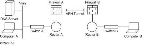
The NAT engine is running on Firewall B. The internal address space behind Firewall B is not routable, and so we have used NAT-ing to make this available. Here is the Diagram we will work with today:
What is NAT?
NAT or Network Address Translation is the process of changing the IP (Source or Destination) of a network packet to remap it to a given address space. We use NAT-ing every day and nearly every time we access an internet resource. Originally NAT was used to help us take care of the dwindling IPv4 public address space (in the mid-1990’s we were quickly running out of IPs), but now NAT also offers a great management, and security function for our modern networks.
Why do we need to use NAT?
The are a large number of scenarios in which we would want to use NAT, we will just cover three. Many company and home networks use a private IP address space (10.x.x.x, 172.16.x.x-172.31.x.x, and 192.168.x.x) per RFC 1918. The nature of these private IP spaces, makes them un-routable on the internet (internet routers will actually drop this traffic altogether). For a device to talk over the internet using one of these IPs we would have to use a NAT device.
Another reason could be two similarly addressed networks. This often happen when companies merge, and before things can be cleaned up they need to operate. Both companies may have use the 10.x.x.x network, and now how two devices for every one IP. The only way to resolve this short of readdressing every device (which usually comes later) is to put in a NAT device so that things can function right now.
A very common use of NAT comes with internet services. When I make my web server available to the internet through my firewall, I want to make sure that you cannot talk to that server directly. A good way to do this is to combine firewall rules with NAT to say something like “If the firewall rules match, then translate the address so that is can be routable”. This is a good security practice, as the network traffic cannot go anywhere without this NAT in place. This is the scenario we will use in our discussion today.
In all of these scenarios we will need to maintain a rule set to tell us what IP we should use in the translation as well as a table (often called an xlate table) to keep track of what IP was translated to what. Here is a sample of this:
Rule(NAT): 10.1.1.1 => 2.2.2.2
Outside IP Inside IP
10.1.1.1 2.2.2.2
NAT vs PAT
NAT is an awesome technology and PAT or Port Address Translation, took it the next step. NAT translates one IP to another. The only challenge with this is that there needs to be a 1:1 match. Consider a large company network with 10,000 network clients inside. For them to each talk on the internet you would need 10,000 external IPs, so that there would be a single external IP for every internal IP.
PAT (which is actually a form of NAT, also sometimes called Port Overload), resolves this problem for us. It not only will change the IP of the packet going on the internet, but also the port will be changed. Given that there can be 65,535 ports per IP address, this means that we (ideally) have a 1:65,535 ratio of external IPs to internal IPs. An AMAZING use of network ports. Again we would have to maintain a rule set and a table of this data. Here is a sample of the rule and extended “xlate” table:
Rule(PAT): 10.x.x.x/8 => 2.2.2.2
Outside IP Outside Port Inside IP Inside Port
10.1.1.1 1025 2.2.2.2 100
10.1.1.2 1025 2.2.2.2 101
10.1.1.3 1025 2.2.2.2 102
Because PAT is so prevalently used, the term NAT and PAT are interchangeably used today in technical discussions. We will follow suit with this today. In the real world, most internet facing servers use true NAT (because of the 1:1), while most clients use PAT to get to the internet.
NAT in our Network
Ok, so now let’s take this data and apply it to our scenario. Here again is where we left off:
L2-[Source MAC: 04-04-04-04-04-04 | Destination MAC: 05-05-05-05-05-05]
L3-[Source IP: 10.1.1.100 | Destination IP: 11.1.1.100]
L4-[Source Port: TCP 1025 | Destination Port: TCP 445]
We are going to keep things simple and use basic NAT for our purposes. Here is the rule set we have on Firewall B:
Rule(NAT): 11.1.1.100 => 192.168.1.100
This NAT rule tells us that to get to the 11.1.1.100 box we would need to change the DestIP from 11.1.1.100 to 192.168.1.100. We would do this, and then use our local routing table (sample below) to determine that Router B is the next hop in the path to the 192.168.1.100 device (through Firewall B’s 30.1.1.1 interface at 08-08-08-08-08-08). We would ARP again (for the IP of Router B 30.1.1.2) on the local network to find the “Next-Hop”, which will be Router B at 09-09-09-09-09-09. Here is our local routing table, our new network packet and the entry in Firewall B’s xlate table:
Network Netmask Gateway Interface
192.168.1.0 255.255.255.0 30.1.1.2 30.1.1.1
10.1.1.0 255.255.255.0 20.1.1.1 PPP
L2-[Source MAC: 08-08-08-08-08-08 | Destination MAC: 09-09-09-09-09-09]
L3-[Source IP: 10.1.1.100 | Destination IP: 192.168.1.100]
L4-[Source Port: TCP 1025 | Destination Port: TCP 445]
Outside IP Inside IP
11.1.1.100 192.168.1.100
Router B would receive this packet and see that it has a local interface on this network (through interface 192.168.1.1 at 10-10-10-10-10-10), and then ARP for the MAC of the device at 192.168.1.100 to get 11-11-11-11-11-11. Here is a sample of Router B’s routing table, and the new network packet:
Network Netmask Gateway Interface
192.168.1.0 255.255.255.0 On-Link 192.168.1.1
30.1.1.0 255.255.255.0 On-Link 30.1.1.2
L2-[Source MAC: 10-10-10-10-10-10 | Destination MAC: 11-11-11-11-11-11]
L3-[Source IP: 10.1.1.100 | Destination IP: 192.168.1.100]
L4-[Source Port: TCP 1025 | Destination Port: TCP 445]
Switch B would receive the network packet and look in its local MAC address table to find that Computer B at 11-11-11-11-11-11 is connected to Int-2. Here is a sample of its MAC address table:
MAC Address Interface
10-10-10-10-10-10 Int-1
11-11-11-11-11-11 Int-2
Finally, Computer B would receive this network packet, and check to see if he is the intended recipient. He would first look at the MAC, and find that it match his local MAC. He would then look at the IP, and find that it matches he local IP. He would finally find the process listening on port TCP 445 and send the data in the packet to that process. (To find this process you can use the PID value found after the listening port in netstat -ano and look it up in this command: tasklist /svc)
So now our little network packet has finished its journey. Next time we are going to walk through the return traffic from Computer B to A and see how the packet changes along the way.
Follow the Bouncing Packet – Series Navigation
Part1: Prerequisites
Part2: Packet Formation
Part3: Switching
Part4: Routing
Part5: Firewalls
Part6: VPN Tunnel
Part7: NAT and PAT
Part8: End-to-End, B-to-A