FtBP: VPN Tunnels
Part 6/8
Last time we talked about how a firewall will handle a network packet, today we will discuss how a packet gets across a VPN Tunnel. Here is where we left off last time with our network packet:
L2-[Source MAC: 04-04-04-04-04-04 | Destination MAC: 05-05-05-05-05-05]
L3-[Source IP: 10.1.1.100 | Destination IP: 11.1.1.100]
L4-[Source Port: TCP 1025 | Destination Port: TCP 445]
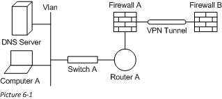
VPN tunnels do not actually read the traffic, they just add some encapsulation and send the packet along its way. Here is our picture for this scenario:
Firewall Sending over VPN Tunnel
We covered last time how the packet was assessed by the filters on Firewall A. What we did not mention is that in the end a firewall also functions like a router. So, the firewall will have to find the way to route the packet to its destination of 11.1.1.100. Here is an excerpt from the firewalls local routing table:
Network Netmask Gateway Interface
12.1.1.0 255.255.255.0 On-link 12.1.1.2
11.1.1.0 255.255.255.0 20.1.1.2 PPP
As you can see the “Interface” to 11.1.1.100 is “PPP” this means that Firewall A will have to send the packet across a VPN tunnel to get it to the 11.1.1.x network.
Basics of VPN Tunnels
A VPN tunnel is already setup between Firewall A and Firewall B. The two firewalls would act as the termination points (or Tunnel Endpoints) for this VPN connection, as these are the places where the tunnel starts and ends. VPN Tunnels are frequently used to secure traffic across an un-trusted network, such as going across an ISP network. There are many kinds of VPN tunnels, but I will stick with just the basics. When you set up VPN tunnels you typically use some data to secure the traffic; ideally this would be a certificate. This enables the traffic to be encrypted across the tunnel, keeping it secure, across possibly unsecure networks.
Packet in the VPN Tunnel
When one tunnel Endpoint (one of the firewalls in this case) gets a packet from its local network, and sees that it needs to send this packet across the VPN segment, the firewall begins to “Encapsulate” the data. What this means is that the firewall uses the secure connection to encrypt the data, and add a new header to the traffic. The old packet header, gets moved into the data payload section of the packet. It does this because on the unsecure network, we do not want anyone to see any piece of the traffic, including the IP addresses on our real networks. We will then have new a new header for layers 2-4 in our network packet. Once traffic enters the VPN Tunnel, it cannot come out except through one of the endpoints (in this case through one of the firewalls).
For our scenario, let’s say that the VPN network is 20.1.1.x, and that the MAC of the PPP (or VPN) interface on Firewall A is 06-06-06-06-06-06, and it’s IP is 20.1.1.1. The MAC of the PPP interface on Firewall B is 07-07-07-07-07-07, and it’s IP is 20.1.1.2.. VPNs typically use UDP 500 for both the SourcePort and the DestPort Here is what our packet would look like on the VPN tunnel:
L2-[Source MAC: 06-06-06-06-06-06| Destination MAC: 07-07-07-07-07-07]
L3-[Source IP: 20.1.1.1 | Destination IP: 20.1.1.2]
L4-[Source Port: UDP 500 | Destination Port: UDP 500]
Data- {[Source MAC: 04-04-04-04-04-04 | Destination MAC: 05-05-05-05-05-05]}
{[Source IP: 10.1.1.100 | Destination IP: 11.1.1.100]}
{[Source Port: TCP 1025 | Destination Port: TCP 445]}
When the packet is received by Firewall B it will perform the normal checks to see that it is the intended recipient. Because Firewall B is the tunnel endpoint it will strip off the encapsulation. The packet will then return to its normal form and Firewall B will begin assessing what to do next with the network packet (which we will get into more next time). Since the VPN data headers are stripped off, the packet we are left with looks exactly like the one we started with today:
L2-[Source MAC: 04-04-04-04-04-04 | Destination MAC: 05-05-05-05-05-05]
L3-[Source IP: 10.1.1.100 | Destination IP: 11.1.1.100]
L4-[Source Port: TCP 1025 | Destination Port: TCP 445]
Follow the Bouncing Packet – Series Navigation
Part1: Prerequisites
Part2: Packet Formation
Part3: Switching
Part4: Routing
Part5: Firewalls
Part6: VPN Tunnel
Part7: NAT and PAT
Part8: End-to-End, B-to-A