FtBP: End-to-End, B-to-A
Part 8/8
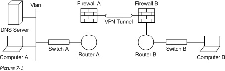
Last time we talked about how a network packet changes through a NAT device, and we finished off the transit of our network packet to Computer B. Today we will follow a network packet from Computer B back to Computer A. Here is the Diagram we will work with:
Packet Creation on Computer B
Computer B will first need to create the network packet. It does this by following the rules outlined in Part 2. First it will use the client application to determine the network ports (because a connection is already established it will use the existing connection; seen w/ netstat -ano). The client will then use ARP to find the MAC of the next hop (in this case the default gateway). Here is Computer B’s configuration, as well as the resulting network packet:
Physical Address. . . . . . . . . : 11-11-11-11-11-11<-Used for SourceMAC
…
IPv4 Address. . . . . . . . . . . : 192.168.1.100 <-Used for SourceIP
Subnet Mask . . . . . . . . . . . : 255.255.255.0
…
Default Gateway . . . . . . . . . : 192.168.1.1
IPv4 Route Table
===========================================================================
Active Routes:
Network Destination Netmask Gateway Interface Metric
0.0.0.0 0.0.0.0 192.168.1.1 192.168.1.100 20
192.168.1.0 255.255.255.0 On-link 192.168.1.100 276
192.168.1.100 255.255.255.255 On-link 192.168.1.100 276
192.168.1.255 255.255.255.255 On-link 192.168.1.100 276
127.0.0.0 255.0.0.0 On-link 127.0.0.1 306
127.0.0.1 255.255.255.255 On-link 127.0.0.1 306
127.255.255.255 255.255.255.255 On-link 127.0.0.1 306
224.0.0.0 240.0.0.0 On-link 127.0.0.1 306
224.0.0.0 240.0.0.0 On-link 192.168.1.100 276
255.255.255.255 255.255.255.255 On-link 127.0.0.1 306
255.255.255.255 255.255.255.255 On-link 192.168.1.100 276
===========================================================================
Persistent Routes:
None
L2-[Source MAC: 11-11-11-11-11-11| Destination MAC: 10-10-10-10-10-10]
L3-[Source IP: 192.168.1.100| Destination IP: 10.1.1.100]
L4-[Source Port: TCP 445 | Destination Port: TCP 1025]
Switching the Network Packet (on Switch B)
Switch B will receive the packet from Computer B and now need to figure out where it goes (See Part 3). It will do this by looking in its local MAC Address Table for a match to the DestMAC. Here is the Switch’s configuration that will cause it to send the packet out Int-1:
MAC Address Interface
10-10-10-10-10-10 Int-1
11-11-11-11-11-11 Int-2
Routing the Network Packet (on Router B)
Router B will then determine if it is the intended recipient by first comparing the DestMAC to its own (on the receiving interface). It will then apply routing rules to find the next hop (See Part 4), and then ARP for that MAC address (it will use the MAC of its outside interface; 09-09-09-09-09-09). Here is the local routing table and the resulting network packet.
Network Netmask Gateway Interface
192.168.1.0 255.255.255.0 On-Link 192.168.1.1
30.1.1.0 255.255.255.0 On-Link 30.1.1.2
10.1.1.0 255.255.255.0 30.1.1.1 30.1.1.2
L2-[Source MAC: 09-09-09-09-09-09| Destination MAC: 08-08-08-08-08-08]
L3-[Source IP: 192.168.1.100| Destination IP: 10.1.1.100]
L4-[Source Port: TCP 445 | Destination Port: TCP 1025]
Processing Through the NAT Engine (on Firewall B)
The NAT device will then need to change back the IP address to something routable on Computer A’s network (See Part 7). Here is the xlate table from Firewall B as well as the resulting network packet:
Outside IP Inside IP
11.1.1.100 192.168.1.100
L2-[Source MAC: 09-09-09-09-09-09| Destination MAC: 08-08-08-08-08-08]
L3-[Source IP: 11.1.1.100| Destination IP: 10.1.1.100]
L4-[Source Port: TCP 445 | Destination Port: TCP 1025]
Transversing the VPN Tunnel
Using its local routing table, Firewall B will then determine that, to get to the 10.1.1.x network, it will need to use its PPP interface. This means that the packet will need to be encapsulated (See Part 6). Firewall B (IP of 20.1.1.2 and MAC of 07-07-07-07-07-07) will ARP for the MAC of Firewall A (IP of 20.1.1.1 and MAC of 06-06-06-06-06-06). Here is the routing table from Firewall B and the resulting network packet:
Network Netmask Gateway Interface
192.168.1.0 255.255.255.0 30.1.1.2 30.1.1.1
10.1.1.0 255.255.255.0 20.1.1.1 PPP
L2-[Source MAC: 07-07-07-07-07-07| Destination MAC: 06-06-06-06-06-06]
L3-[Source IP: 20.1.1.2 | Destination IP: 20.1.1.1]
L4-[Source Port: UDP 500 | Destination Port: UDP 500]
Data- {[Source MAC: 09-09-09-09-09-09 | Destination MAC: 08-08-08-08-08-08]}
{[Source IP: 11.1.1.100 | Destination IP: 10.1.1.100]}
{[Source Port: TCP 445 | Destination Port: TCP 1025]}
Firewall A will receive this packet on its PPP interface, and strip off the encapsulation to be left with:
L2-[Source MAC: 09-09-09-09-09-09| Destination MAC: 08-08-08-08-08-08]
L3-[Source IP: 11.1.1.100| Destination IP: 10.1.1.100]
L4-[Source Port: TCP 445 | Destination Port: TCP 1025]
Applying the Firewall Filters
Firewall A will then make sure that this packet meets its filter rules (See Part 5. After the rules are checked it will act as a router and find the next hop in delivery of this packet using its local routing table. It will then ARP for Router A’s IP (Router A at 12.1.1.1 and MAC of 04-04-04-04-04-04; out Firewall A’s inside interface at 12.1.1.2 and MAC of 05-05-05-05-05-05). Here is Firewall A’s filter rule set, it local routing table, and the resulting network packet:
(1a)SourceIP (1b)NetMask (2)SourcePort (3a)DestIP (3b)NetMask (4)DestPort
10.1.1.x /24 Any 11.1.1.x /24 TCP 445
11.1.1.x /24 TCP 445 10.1.1.x /24 Any
Network Netmask Gateway Interface
12.1.1.0 255.255.255.0 On-link 12.1.1.2
11.1.1.0 255.255.255.0 20.1.1.2 PPP
10.1.1.0 255.255.255.0 12.1.1.1 12.1.1.2
L2-[Source MAC: 05-05-05-05-05-05| Destination MAC: 04-04-04-04-04-04]
L3-[Source IP: 11.1.1.100| Destination IP: 10.1.1.100]
L4-[Source Port: TCP 445 | Destination Port: TCP 1025]
Routing the Network Packet (on Router A)
Router A will then determine if it is the intended recipient by first comparing the DestMAC to its own (on the receiving interface). It will then apply routing rules to find the next hop (See Part 4), and then ARP for that MAC address (The MAC of 10.1.1.100 since it is on the local link which is 01-01-01-01-01-01, and it will use the MAC of its inside interface; 03-03-03-03-03-03). Here is the local routing table and the resulting network packet.
Network Netmask Gateway Interface
10.1.1.0 255.255.255.0 On-link 10.1.1.1
11.1.1.0 255.255.255.0 12.1.1.2 12.1.1.1
L2-[Source MAC: 03-03-03-03-03-03| Destination MAC: 01-01-01-01-01-01]
L3-[Source IP: 11.1.1.100| Destination IP: 10.1.1.100]
L4-[Source Port: TCP 445 | Destination Port: TCP 1025]
Switching the Network Packet (on Switch A)
Switch B will receive the packet from Computer B and now need to figure out where it goes (See Part 3). It will do this by looking in its local MAC Address table for a match to the DestMAC. Here is the Switch’s configuration that will cause it to send the packet out Int-1:
MAC Address Interface
01-01-01-01-01-01 Int-1
02-02-02-02-02-02 Int-2
03-03-03-03-03-03 Int-3
Receiving the Network Packet
Computer A will then receive the network packet and check to make sure that it is the intended recipient. It will first look at the MAC address for a match to DestMAC. Then it will look at the IP address for a match to DestIP. When it finds that these two match it will send the data in the packet up the stack to the upper layer protocols.
Summary
So there we go. Amazing that something that happens so naturally is so lengthy and complicated. We barely scratched the surface in this series, but hopefully this helped to grasp a conceptual understanding of how packets flow within a network.
When I was first learning networking my mentor gave me a Chart, much like the one below, to track how a packet changes from hop to hop. If you are interested, I would encourage you to practice filling this out; it was a great learning tool for me. Hopefully this will help you too:
Packet flow from Computer A to Computer B
| At Device | SrcMAC | SrcIP | SrcPort | DestMAC | DestIP | DestPort |
| Computer A | 01-01-01-01-01-01 | 10.1.1.100 | TCP 1025 | 03-03-03-03-03-03 | 11.1.1.100 | TCP 445 |
| Router A | 04-04-04-04-04-04 | 10.1.1.100 | TCP 1025 | 05-05-05-05-05-05 | 11.1.1.100 | TCP 445 |
| Firewall A | 06-06-06-06-06-06 | 20.1.1.1 | UDP 500 | 07-07-07-07-07-07 | 20.1.1.2 | UDP 500 |
| Firewall B | 08-08-08-08-08-08 | 10.1.1.100 | TCP 1025 | 09-09-09-09-09-09 | 192.168.1.100 | TCP 445 |
| Router B | 10-10-10-10-10-10 | 10.1.1.100 | TCP 1025 | 11-11-11-11-11-11 | 192.168.1.100 | TCP 445 |
Packet flow from Computer B to Computer A
| At Device | SrcMAC | SrcIP | SrcPort | DestMAC | DestIP | DestPort |
| Computer B | 11-11-11-11-11-11 | 192.168.1.100 | TCP 445 | 10-10-10-10-10-10 | 10.1.1.100 | TCP 1025 |
| Router B | 09-09-09-09-09-09 | 192.168.1.100 | TCP 445 | 08-08-08-08-08-08 | 10.1.1.100 | TCP 1025 |
| Firewall B | 07-07-07-07-07-07 | 20.1.1.2 | UDP 500 | 06-06-06-06-06-06 | 20.1.1.1 | UDP 500 |
| Firewall A | 05-05-05-05-05-05 | 11.1.1.100 | TCP 445 | 04-04-04-04-04-04 | 10.1.1.100 | TCP 1025 |
| Router A | 03-03-03-03-03-03 | 11.1.1.100 | TCP 445 | 01-01-01-01-01-01 | 10.1.1.100 | TCP 1025 |
Follow the Bouncing Packet – Series Navigation
Part1: Prerequisites
Part2: Packet Formation
Part3: Switching
Part4: Routing
Part5: Firewalls
Part6: VPN Tunnel
Part7: NAT and PAT
Part8: End-to-End, B-to-A