FtBP: Routing
Part 4/8
In a previous discussion (Part 2) we covered the formation of a network packet in preparation to send that packet on the wire. Today we will cover the packet’s travel through its local router. Let’s start by reviewing what we had in our network packet. Here is where we left off:
L2-[Source MAC: 01-01-01-01-01-01 | Destination MAC: 02-02-02-02-02-02]
L3-[Source IP: 10.1.1.100 | Destination IP: 10.1.1.101]
L4-[Source Port: UDP 1025 | Destination Port: UDP 53]
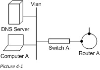
One key to remember as we go about this series is the role that each network device holds and where it sits in the OSI model. This will help us to know what we can use to route the traffic. In this article we are going to stick with routing, which is a Layer 3 function. Because of this we will only be able to look at the data contained in layers 2 and 3 of the network packet (or the Source and Destination MAC addresses, and Source and Destination IP addresses). Here is our picture for this scenario:
IP Address Basics
Lets start today by taking a look at the attributes of an IP address. Unlike MAC addresses, IP addresses are Hierarchal. IP addresses are assigned, by us, to a device, and can be readily be changed to suit our needs. This means that we can group clients together and say something like “they are on the 10.1.1 net” (in this case all IP addresses on that network would start with 10.1.1.x). Because IP addresses are controlled by us, and because they are hierarchical, we can not only group computers together into a network, but we can also group networks together into a supernet (i.e. – would could take networks 10.1.1.x through 10.1.255.x and summarize them as 10.1.x.x).
Clients Checks for IP
Much like we discussed in the previous article, when we (in this case the DNS server) receive a network packet we first check to make sure that this packet was destined for us. Last time we went over this in the perspective of the MAC address, but we do the same for the IP address as well, with one change. Instead of looking for just the IP address configured on the receiving interface, we look for a match to the IP to any IP configured on the box. So in the case of routing the packet to the DNS server, we would look to see if the DestIP value in the received network packet matched any of our own.
Client Sending Packet “Off-Network”`
Previously in our scenario, we were sending a packet to the local DNS server on the same VLAN. To continue with that, lets now take the next step and say that, what we were contacting the local DNS server for was the IP address of Computer B, which we found was 11.1.1.100, to initiate a file transfer (using CIFS, making our DestPort TCP 445, and the SourcePort, ephemeral). Let’s take a quick look back to the topics we covered in Part 2 of this series to see how Computer A would now form the network packet. Here again is our local routing table:
IPv4 Route Table
===========================================================================
Active Routes:
Network Destination Netmask Gateway Interface Metric
0.0.0.0 0.0.0.0 10.1.1.1 10.1.1.100 20
10.1.1.0 255.255.255.0 On-link 10.1.1.100 276
10.1.1.100 255.255.255.255 On-link 10.1.1.100 276
10.1.1.255 255.255.255.255 On-link 10.1.1.100 276
127.0.0.0 255.0.0.0 On-link 127.0.0.1 306
127.0.0.1 255.255.255.255 On-link 127.0.0.1 306
127.255.255.255 255.255.255.255 On-link 127.0.0.1 306
224.0.0.0 240.0.0.0 On-link 127.0.0.1 306
224.0.0.0 240.0.0.0 On-link 10.1.1.100 276
255.255.255.255 255.255.255.255 On-link 127.0.0.1 306
255.255.255.255 255.255.255.255 On-link 10.1.1.100 276
===========================================================================
Persistent Routes:
None
Using this table we will try to find a match for the route to 11.1.1.100 (The IP of Computer B), which will also become our DestIP in the new packet. Looking at the local routing table we can see that the best match is 0.0.0.0, since none of the others can get us there. This means that we will send our packet out the interface addressed 10.1.1.100, and that our next hop (or DestMAC) will be that of 10.1.1.1, which is also our default gateway.
We will again send an ARP to our local network, this time for the IP of 10.1.1.1. This IP belongs to the local router as the network interface for the 10.1.1.x network. The router will receive this ARP and respond with its network interface’s MAC. For our purposes, let’s say that this is 03-03-03-03-03-03, and that the switch has already learned that this router interface is plugged into Int-3. Here is the updated MAC Address Table, belonging to Switch A:
MAC Address Interface
01-01-01-01-01-01 Int-1
02-02-02-02-02-02 Int-2
03-03-03-03-03-03 Int-3
So now we have all the parts of our new network packet (setting the SourcePort to be TCP 1025, making it look like this:
L2-[Source MAC: 01-01-01-01-01-01 | Destination MAC: 03-03-03-03-03-03]
L3-[Source IP: 10.1.1.100 | Destination IP: 11.1.1.100]
L4-[Source Port: TCP 1025 | Destination Port: TCP 445]
There is something very interesting that we learn from this packet, that I want to take a second to note. We will be switching this packet to Router A (See DestMAC), but we will be Routing the packet to Computer B (See DestIP). This is why the DestMAC value is often referred to as the “Next Hop”, and you will be seeing how it changes throughout this sample connection.
IP Routing Basics
So after Switch A does its job Router A receives the packet on its interface (10.1.1.1), and now has to decide what to do with it (After doing the assessments on whether it is the intended recipient) . To really simplify things, Routers in a network share information about what VLANs they are directly connected to. This information propagates around a network in “Route Advertisements” so that every device has the same knowledge of network routes. The interface that the “Route Advertisement” is received on is recorded, so that the router knows, that “to get to those subnets I need to send the packet out this interface”. Let’s look at a sample routing table to help make sense of things. Here is a simplified sample routing table that we will use for Router A:
Network Netmask Gateway Interface
10.1.1.0 255.255.255.0 On-link 10.1.1.1
11.1.1.0 255.255.255.0 12.1.1.2 12.1.1.1
In this routing table we can see that the 10.1.1.x network is connected to Router A directly, through interface 10.1.1.1. We can also see that to get to the 11.1.1.x network we need to go through the device located at 12.1.1.2, through interface 12.1.1.1. So Router A will then try to learn the MAC address of the device at 12.1.1.2.
Routers as ARP Clients
In many ways routers act just like computers do on the local network. One of these ways is that router are ARP clients, meaning that they will use the ARP protocol to resolve IPs to MAC addresses. There is one pivotal difference though, and that is that routers maintain a local ARP table, which is a mapping of IP to MAC. It populates this table with every ARP that it has preformed, and given that it is always involved with clients reaching off their local network, that is a lot. For our purposes let’s say that Router A already has looked for the MAC of 12.1.1.2, and has it stored in its table. Here is what a sample would look like:
IP Address MAC Address
10.1.1.100 01-01-01-01-01-01
12.1.1.2 05-05-05-05-05-05
Now when Router A finds that the packet needs to be sent to the device at 12.1.1.2 (out its interface 12.1.1.1 at 04-04-04-04-04-04 which will become its SourceMAC) for further routing it knows to set the DestMAC or “Next Hop” value to 04-04-04-04-04-04. Here is the packet headers now:
L2-[Source MAC: 04-04-04-04-04-04 | Destination MAC: 05-05-05-05-05-05]
L3-[Source IP: 10.1.1.100 | Destination IP: 11.1.1.100]
L4-[Source Port: TCP 1025 | Destination Port: TCP 445]
Next time we will discuss how the packet transverses the firewall.
Follow the Bouncing Packet – Series Navigation
Part1: Prerequisites
Part2: Packet Formation
Part3: Switching
Part4: Routing
Part5: Firewalls
Part6: VPN Tunnel
Part7: NAT and PAT
Part8: End-to-End, B-to-A