FtBP: Packet Formation
Part 2/8
Packets on the wire (purposely repeated)
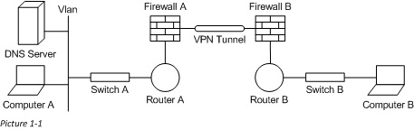
As we go through this series we will go over some examples to help understand the progression of a network packet throughout a network segment. We will start off simple and grow to more and more complicated packet transfers, but before we get to the wire we will need to look at how the data is packaged, and so how the packet forms. Please forgive the rudimentary drawings, they are done to preserve load times on this webpage. Here is the complete network diagram we will be working with. In our discussion we will walk through piece by piece and end with a view of the packets progression in entirety.
Packet Formation
When looking at how a packet transverses the network it is important to understand how the data in the initial packet get populated. In this part of the series we will go through a client’s (the initiator of any connection) initial creation of a packet. Quite a bit of this, such as the client redirector, is beyond the scope of this article, what we will cover comes after the client has determined that this data is destined for a remote host, and how the information needed is gathered. If you remember from the first article in this series, we are going to use the format below as an example of the network TCP/IP header of a packet. This packet has both a “Source” and “Destination” context for each of the MAC, IP, and Port values. We will need to gather this data locally as well as remotely.
L2-[Source MAC: XX-XX-XX-XX-XX-XX | Destination MAC: XX-XX-XX-XX-XX-XX]
L3-[Source IP: X.X.X.X | Destination IP: X.X.X.X]
L4-[Source Port: TCP/UDP X | Destination Port: TCP/UDP X]
Getting the Data
When a client first recognizes that to fulfill a need of a local application, it needs to go over the network, it captures some important data. The first of these is the name (the DNS record, or in rare cases the IP address) of the remote server that is providing this service. The client’s local application is responsible for providing this initial data. The application also provides at least the remote port, and in some cases the local port as well.
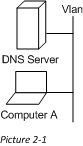
For our purposes today, let’s look at one of the most common of all network clients, the DNS client resolver. Since most of our connections are done by server or application name, DNS is at the core of almost all our network connections. As you can see in the diagram (picture 2-1) we have a DNS server on the client’s local subnet. Let’s pretend you entered www.Cbfive.com into your internet browser. Names are something that only us Humans really use. In the computer world this name first needs to be resolved to an IP address to be able to send a packet on the wire. So, now you need to use DNS to resolve the name to an IP address that the computer can use. We will focus on just the DNS lookup part of this.
Keep in mind that we need to populate the packet with SourceMAC, SourceIP, SourcePort, DestMAC, DestIP, and DestPort. The application (the DNS client resolver) may dictate the SourcePort (Though not in this case) and will often dictate the DestPort, which in this case will be UDP 53. The DestIP will be gotten from the interface configuration by the DNS client, since we are looking for a DNS server. This IP will then be provided to the TCPIP driver. Since we are keeping things simple I will not get into the DNS client resolver’s behavior in this article (look for a future post), it is enough to assume that we are going to use the first DNS server listed in an Ipconfig /all output (though this is not exactly where a DNS client looks for this information), here is an excerpt from a sample we will use for this scenario:
Physical Address. . . . . . . . . : 01-01-01-01-01-01 <-Used for SourceMAC
…
IPv4 Address. . . . . . . . . . . : 10.1.1.100 <-Used for SourceIP
Subnet Mask . . . . . . . . . . . : 255.255.255.0
…
Default Gateway . . . . . . . . . : 10.1.1.1
…
DNS Servers . . . . . . . . . . . : 10.1.1.101 <-Used for DestIP
Note: From this output we can glean the values of SourceMAC, SourceIP, and DestIP
We will then use the DestIP (Equal to 10.1.1.101) to find the DestMAC, which is sometimes called the next hop. We will first determine the interface/gateway to use to talk to the remote server. This determination is done through the local routing table. Here is a sample output (From a Win7 Client) Which can be gathered by using netstat -r, or route print¸ or…
IPv4 Route Table
===========================================================================
Active Routes:
Network Destination Netmask Gateway Interface Metric
0.0.0.0 0.0.0.0 10.1.1.1 10.1.1.100 20
10.1.1.0 255.255.255.0 On-link 10.1.1.100 276
10.1.1.100 255.255.255.255 On-link 10.1.1.100 276
10.1.1.255 255.255.255.255 On-link 10.1.1.100 276
127.0.0.0 255.0.0.0 On-link 127.0.0.1 306
127.0.0.1 255.255.255.255 On-link 127.0.0.1 306
127.255.255.255 255.255.255.255 On-link 127.0.0.1 306
224.0.0.0 240.0.0.0 On-link 127.0.0.1 306
224.0.0.0 240.0.0.0 On-link 10.1.1.100 276
255.255.255.255 255.255.255.255 On-link 127.0.0.1 306
255.255.255.255 255.255.255.255 On-link 10.1.1.100 276
===========================================================================
Persistent Routes:
None
Looking at the routing table a little binary math is needed. It is enough to know that when focusing on each octet (the number before or after a “.”) 255 means an exact match, and 0 means anything. So if we know we are looking for 10.1.1.101 then the third line (The rule that covers IPs 10.1.1.0-10.1.1.255) is what we will apply. The “Gateway”, you’ll notice, is “On-Link”, meaning the local subnet. Because of this to receive a IP to MAC mapping we will use the ARP protocol on the wire. The question will go out something like “Who has 10.1.1.101?” The subnet local host (the DNS server) will then respond to the ARP question with its MAC address, which the client will in turn use to populate the packet header under DestMAC (For our purposes let’s say that this is 02-02-02-02-02-02).
So altogether now we have everything but the Source Port. We know the protocol will be UDP and because no port is specified by this particular client service (The DNS Client Resolver) we will use an ephemeral port (Also known as a “High Port”; i.e. – 1025-65535). For our purposes, let’s pretend we use UDP 1025 as our SourcePort. Altogether this makes our packet header look like this:
L2-[Source MAC: 01-01-01-01-01-01 | Destination MAC: 02-02-02-02-02-02]
L3-[Source IP: 10.1.1.100 | Destination IP: 10.1.1.101]
L4-[Source Port: UDP 1025 | Destination Port: UDP 53]
Ok, so now we have our packet formed (at least the header). In our next part we will explore how the frame is switched, and what the receiving host does with it when it receives it.
Follow the Bouncing Packet – Series Navigation
Part1: Prerequisites
Part2: Packet Formation
Part3: Switching
Part4: Routing
Part5: Firewalls
Part6: VPN Tunnel
Part7: NAT and PAT
Part8: End-to-End, B-to-A